Scheduler for Arduino – Blink LEDs periodically
#include
//variables for LED blinking
boolean flag0 = 0;
boolean flag1 = 0;
boolean flag2 = 0;
boolean flag3 = 0;
boolean toggle0 = 0;
boolean toggle1 = 0;
boolean toggle2 = 0;
boolean toggle3 = 0;
//counter for tasks
long int count = 0;
//variable to store number of times button pressed
int buttonpress = 0;
void setup()
{
//set pins as outputs
pinMode(10, OUTPUT);
pinMode(11, OUTPUT);
pinMode(12, OUTPUT);
pinMode(13, OUTPUT);
//Serial display to show number of times button pressed
Serial.begin(9600);
pinMode(A0, INPUT);
//Enable watchdog timer with timeout of 4 seconds
wdt_enable(WDTO_4S);
cli();//stop interrupts
//set timer1 interrupt at 1Hz
TCCR1A = 0;// set entire TCCR1A register to 0
TCCR1B = 0;// same for TCCR1B
TCNT1 = 0;//initialize counter value to 0
// set compare match register for 1 hz increments
OCR1A = 15625;// = (16*10^6) / (15625 * 1024) (1024 Prescalar)
// turn on CTC mode
TCCR1B |= (1 << WGM12);
// Set CS12 and CS10 bits for 1024 prescaler
TCCR1B |= (1 << CS12) | (1 << CS10);
// enable timer compare interrupt
TIMSK1 |= (1 << OCIE1A);
PCICR =0x02; // Enable PCINT1 interrupt
PCMSK1 = 0b00000001; // Select Pin A0
sei();//allow interrupts
}//end setup
ISR(TIMER1_COMPA_vect)
{//timer1 interrupt 1 Hz
count++;
if(count == 801)
{
count = 0;
}
flag0 = 0;
if(count % 2 == 0)
flag1 = 0;
if(count % 4 == 0)
flag2 = 0;
if(count % 8 == 0)
flag3 = 0;
}
ISR(PCINT1_vect)
{ // Interrupt service routine. Interrupt on A0 pin change
if (digitalRead(A0)==0)
{
buttonpress++;
Serial.print("button press = ");
Serial.println(buttonpress);
}
}
void loop()
{
if(flag0 == 0) // Task1 – Blink LED every 1 s on pin 10
{
digitalWrite(10,toggle0);
toggle0 = !toggle0;
flag0 = 1;
}
if(flag1 == 0) // Task2 – Blink LED every 2 s on pin 11
{
digitalWrite(11,toggle1);
toggle1 = !toggle1;
flag1 = 1;
}
if(flag2 == 0) // Task3 – Blink LED every 4 s on pin 12
{
digitalWrite(12,toggle2);
toggle2 = !toggle2;
flag2 = 1;
}
if(flag3 == 0) // Task 4 – Blink LED every 8 s on pin 13
{
digitalWrite(13,toggle3);
toggle3 = !toggle3;
flag3 = 1;
}
//Reset the watchdog timer
wdt_reset();
}
Book Review : The 3 mistakes of my life
Filed under: Entertainment | Tags: Books, Business, Chetan Bhagat, Cricket, Novels
 Comments (33)
Oops! I did a mistake by reading this book. That was my nth mistake in life (Of course n being a positive integer and much greater than 0). Okay! Jokes apart, this is the third book by Chetan Bhagat, who is back to India now and has dedicated the book ‘to the country, which called him back’.
The 3 mistakes of my life is a story of three best friends (sounds familier isn’t it?) based in Ahmedabad. Govind is the narrator of the story. He is a born businessman and dreams of owning a big business someday. He is in love with Vidhya, who happens to be the sister of one of his best friend Ishaan. Ishaan is very passionate guy who loves cricket. He was the best cricket player in his school and aspired to be in Indian Cricket team. But he performs badly in the selections and thus ends up getting rejected. His parents want him to join Army, which he hates. Govind’s other friend is Omi, who is the son of a priest of a local temple. Omi doesn’t know what to do in his life, but he doesn’t want to continue his father’s profession. So he sticks around with his friends. Then there is Ali, a young boy who is a gifted cricketer, but is more interested in playing marbles. Ishaan spots him and starts coaching him with a hope to see him in Indian Cricket team one day.
The book starts very well giving a detailed description of each character. Chetan’s style of narration has definitely improved since his first book FPS . Half way through the book, it gets dull, and at the end the climax part sucks. Lot of communal violence is brought in, and it was really a pain reading the final few chapters. I hope Chetan comes up with science fiction novels in future.
PID Controller Simplified
Filed under: Control Systems, Technology | Tags: Control Systems, Controller, Matlab, PID Controller, Step response
Comments (38) This is an attempt to explain PID controller with minimum use of maths.
A simple closed loop control system consisting of a controller and a process (or plant) is shown below.

The input to the system is the ‘setpoint’, ie the desired output. The input to the controller is the error.
Error = Present Output – Setpoint.
The two steps in the design of a control system are –
1. Mathematically model the plant to be controlled.
2. Design the Controller.
The block diagram of a PID controller is shown below –
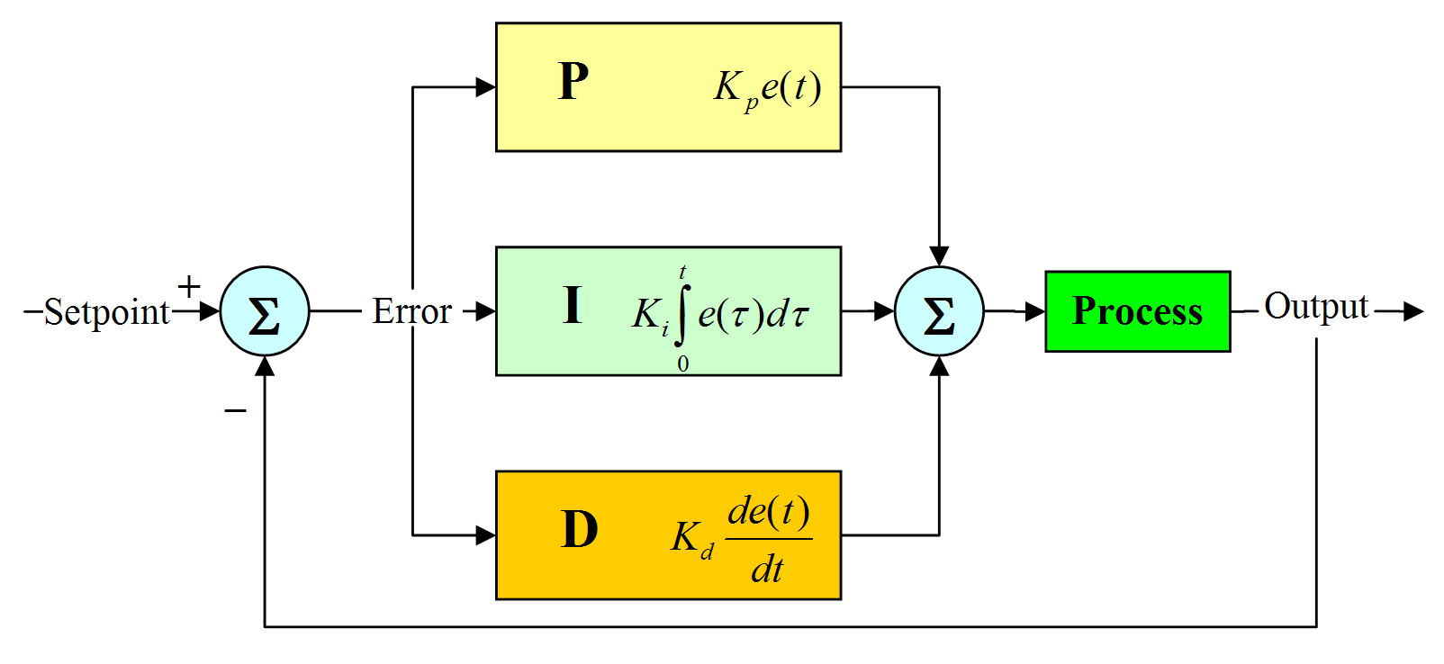
A PID controller consists of a Proportional element, an Integral element and a Derivative element, all three connected in parallel. All of them take the error as input. Kp, Ki, Kd are the gains of P, I and D elements respectively.
The best way to understand something is by simulating it. So I simulated a PID controller in matlab. The matlab code is provided at the end of this article.
Let me assume a suitable mathematical model for the plant and then go ahead with designing the controller.
Let the transfer function of the plant be 1 / ( s^2 + 20s + 30 ).
The step response of a system is the output of the system when the input to the system is a unit step. The open loop step response of the above plant is –
(Click on the image to get an enlarged picture)

It can be seen that the step response output is close to 0.035. The steady state error = 1-0.035 = 0.965. That’s quite high! Also observe that the settling time is around 3 sec.
Now lets see what is the effect of PID controller on the system response.
Lets see the effect of proportional element on the system output.
Keeping Kp = 10, Ki = 0, Kd = 0 the step response of the system is

The output is now 0.25. Much better than the open loop response! (The curve in red shows the open loop step response of the plant)
Now let me increase the Kp further and observe the response.
Keeping Kp = 100, Ki = 0, Kd = 0 the step response of the system is

The output is now 0.77. So it’s clear now that increasing Kp will reduce the steady state error.
Keeping Kp = 200, Ki = 0, Kd = 0 the step response of the system is

The output is around 0.87. Also observe that the ripples have started appearing in the output. If Kp is increased further it will only lead to increase in ripples or overshoot. The rise time also has decreased. Also observe that there is a small steady state error (1 – 0.87 = 0.13).
Conclusion –
Increasing Kp will reduce the steady state error.
After certain limit, increasing Kp will only increase overshoot.
Kp reduces rise time.
Now lets keep Kp fixed. Lets start varying Ki.
Keeping Kp = 200, Ki = 10, Kd = 0 the step response of the system is

The output is now close to 0.99. That’s very close to the setpoint. But observe that settling time has increased.
Keeping Kp = 200, Ki = 200, Kd = 0 the step response of the system is

Observe that rise time has now reduced and steady state error is very small.
Keeping Kp = 200, Ki = 300, Kd = 0 the step response of the system is

Observe that steady state error is close to 0 now. But increasing Ki has resulted in overshoot.
Further increasing Ki will only increase overshoot.
Conclusion –
Ki eliminates the steady state error.
After certain limit, increasing Ki will only increase overshoot.
Ki reduces rise time.
Now lets Keep Ki fixed and start varying Kd.
Keeping Kp = 200, Ki = 300 and Kd = 10.

Wow! What a response! Where is the overshoot? It has disappeared. There is a reduction in settling time as well.
Increasing Kd further will only result in response getting worsened.
Conclusion –
Kd decreases the overshoot.
Kd reduces settling time.
So the ideal PID values for our plant is Kp = 200, Ki = 300 and Kd = 10.
The above process is known as manual tuning of PID.
Here is the matlab code used to simulate PID –
(The below code is written by me. So please let me know if you find any bugs!)
num=1;
den=[1 20 30];
Plant = tf(num,den);
step(Plant,’r’);
hold on;
Kp=200;
P_Sys = tf(Kp,1);
Ki=300;
den2=[1 0];
I_Sys=tf(Ki,den2);
Kd=10;
num3=[Kd 0];
D_Sys=tf(num3,1);
PI=parallel(P_Sys,I_Sys);
PID=parallel(PI,D_Sys);
OpenLoop=series(PID,Plant);
ClsdLoop = feedback(OpenLoop,[1]);
step(ClsdLoop,’b’);
Flash Memory – The Little Champ !
Filed under: Technology | Tags: EEPROM, Flash Memory, Hard Disk Drive, Hybrid Drive, Solid State Drives
Comments (1) 
What’s common between a Pen Drive, SD, Mini SD and Micro SD Cards? All of them hold large amount of data in a tiny space. The advent of flash memory has made it possible to shrink the size of memory chips and has found its place in cell phones, Cameras, PDA’s and other portable devices.
Flash is a non volatile memory meaning the data is retained even when there is no power supply. It’s a particular type of EEPROM (Electrically Erasable Programmable Read Only Memory) that is erased and programmed in large blocks. EEPROMs are realized as arrays of floating gate transistors (MOSFETs to be more precise) and hence occupy lesser space. But there’s one characteristic of Flash that makes it unique and advatageous over the typical EEPROM – the electrical interface of a Flash differs from that of the typical EEPROM. While Flash is read / erased in large blocks, EEPROMs are read/erased bytewise as it has dedicated circuits for each byte. And this characteristic of Flash makes it more affordable.
Solid State Drives (SSD), which use Flash memory, consume only one tenth of the power as that used by Magnetic hard drives. With no moving parts, they are more reliable, rugged and compact. Apple’s MacBook Air, the thinnest laptop in the world, is the first gadget to sacrifice hard disk and optical disk drives in favour of the Solid State Drives. A MacBook Air with 64 GB Solid State Drive costs around $3000 whereas the one with 80 GB Hard Disk Drive costs $1799. Apparently one would have to pay more for a Solid State Drive but it’s worth the benefits it offers. Unlike a Hard Disk even if your laptop is dropped often, the drive won’t crash.
Samsung has unveiled a Hybrid Drive which has a buffer of 128/256 MB cache consisting of Flash memory. By using this large buffer for data storage, the platters of the hard drive are at rest almost all of the time, instead of constantly spinning, as they are in the current hard drives. The data to be stored is temporarily written into the cache, and once the cache is full the data is written into the disk resulting in decreased power consumption and lesser write times.
In future, as prices continue to fall, the Solid State Drives are likely to replace conventional Magnetic Drives. The future of FLASH looks BRIGHT!

